What is the shock response spectrum test?
— Part 3 How many types of mechanical shock test device?
The main types of mechanical shock test devices are as follows:
1) Fixed resonance frequency test device
2) Adjustable resonant frequency test device
3) Adopt drop-type shock table
4) Pendulum shock response spectrum testing machine
5) Pneumatic shock response spectrum test system
1) Fixed resonance frequency test device:
A representative fixed resonance frequency test device (show in Figure 6). This type of mechanical impulse pyroshock simulator (MIPS) uses a pneumatic hammer shock method. The hammer head hits the plate-shaped device from top to bottom to make the product undergo a shock load similar to explosive shock. This device has the advantage of adjusting multiple parameters to meet different test conditions. It is an aluminum plate placed on a foamed plastic cushion. The shock load is generated by a pneumatic actuator. The actuator is mounted on a bridge and can be moved to change the shock position. The shock hammer can be replaced to produce different shock durations. This device can have different forms, and the shock method (shock source) can also be varied. They have a certain degree of versatility, but they need to be debugged before the test. The time it takes to debug depends on the experience of the tester.
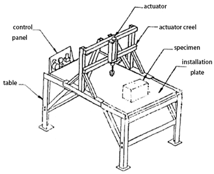
Figure 6 Fixed resonance frequency shock response spectrum test device
2) Adjustable resonant frequency test device
In order to make the test device more versatile and easily meet different test conditions, it is natural to hope that the resonance frequency of the test device can be changed. The adjustable resonant frequency test device is to fix an aluminum beam on a concrete base. The two ends of the beam are equivalent to fixed supports. Therefore, the resonance frequency of the device is inversely proportional to the square of the beam length. Change the length between the fixed ends, different resonance frequencies can be obtained to meet different test requirements, and appropriate fine-tuning can be made to adapt to subtle changes in conditions. Figure 7 is a simplified diagram of the adjustable resonant frequency test device. Its structure is not complicated, but the practical design can meet the test requirements of larger samples.
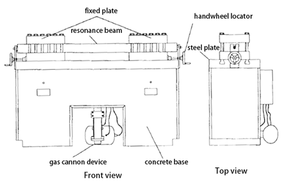
Figure 7 Adjustable resonant frequency test device
3) Adopt drop-type shock table
Figure 8 shows the device that is transformed from the existing common vertical shock table to realize the shock response spectrum. This device uses four or more screws to fix a resonance plate on the base. The resonance plate is equipped with a test sample on the outside of the supporting screw, and a damping pad is installed at the middle position to generate response waveforms with different pulse widths. The shock response spectrum test can be carried out with the drop type vertical shock table, and the shock response spectrum line can be adjusted within a certain range. The device is simple and the cost is low. Only one resonance plate is required.
However, due to the limitation of the installation position, the test product can only be installed at a position far away from the shock head, so the energy transmitted through the resonance plate is greatly attenuated with distance. Moreover, the response of the entire resonator board varies greatly with different positions. Therefore, this method is only suitable for samples with a small weight and occupying a small area of the resonator plate (below 10kg), which has great limitations. In addition, because the response values of different points on the resonance plate vary greatly, and the test accuracy of the sample is poor, it is not recommended to use this method for shock response spectrum test.
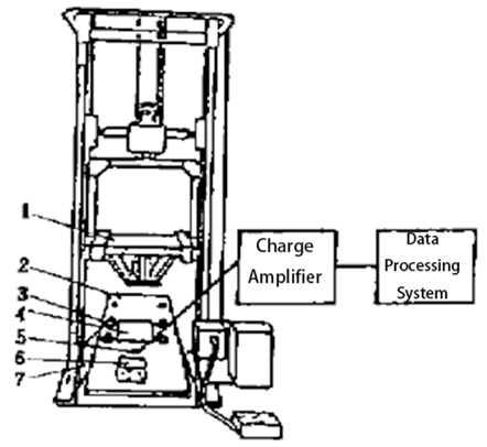
1. shock head 2. Resonance plate 3. Fastening screw 4. Damping pad 5. Acceleration sensor 6. Sample 7. shock table base
Figure 8 Shock response spectrum test device of drop-type shock table
4) Pendulum shock response spectrum testing machine
At present, the widely used shock response spectrum equipment is a pendulum-type shock response spectrum testing machine, the basic structure of which is shown in Figure 9. The bracket and buffer are placed on the base, and the resonance plate is installed on the bracket and can slide. When the hammer hits the resonance plate, it causes the resonance plate to vibrate. The acceleration sensor collects the shock signal, and then the computer system performs data processing to obtain the shock response spectrum curve.
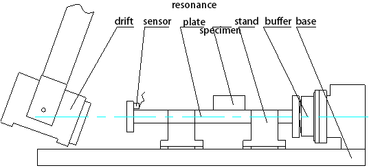
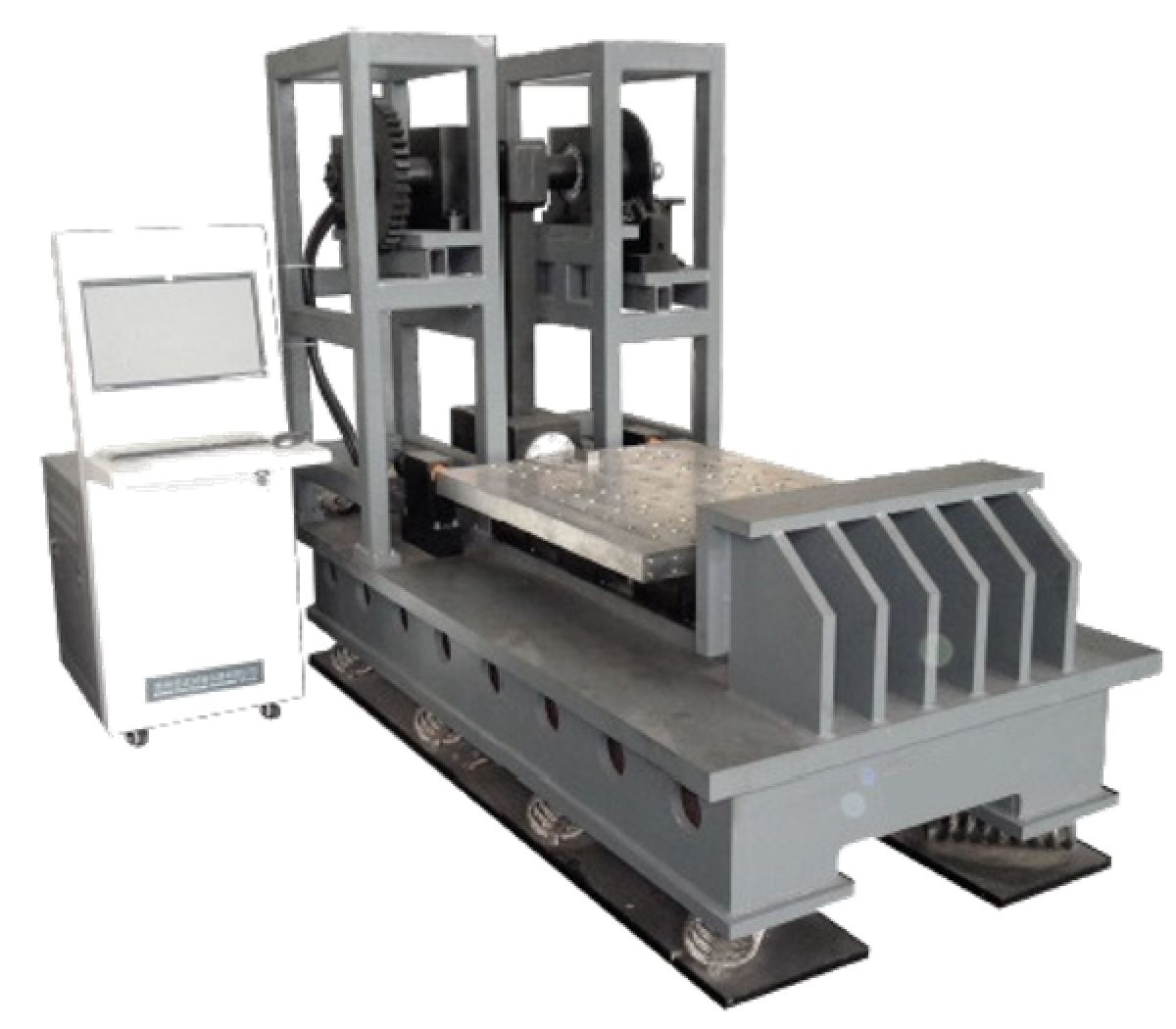
Figure 9 Pendulum shock response spectrum testing machine
5) Pneumatic shock response spectrum test system
In order to overcome the shortcomings of the existing technology, our company has newly developed a pneumatic high acceleration level shock response spectrum test system with compact structure, short stroke, large excitation energy, safety and environmental protection, which can overcome the disadvantages of existing pendulum shock response spectrum test machine with small excitation energy, large space occupation, installation and maintenance inconvenience.
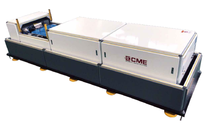
Figure 10 KRD15 Series Horizontal Shock Response Test System
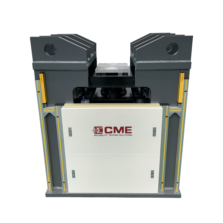
Figure 11 KRD14 Series Vertical Shock Response Test System
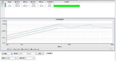
Software interface


