


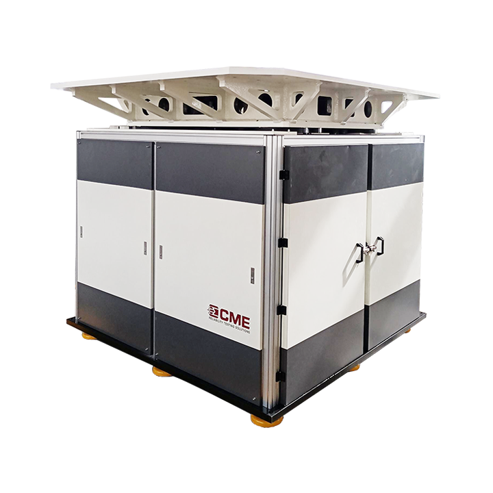
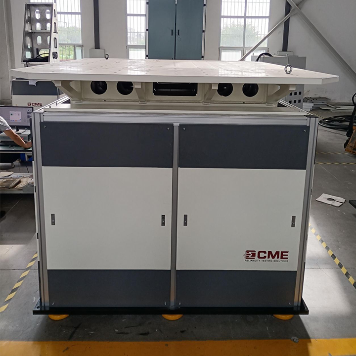
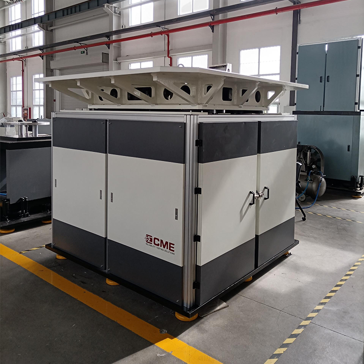
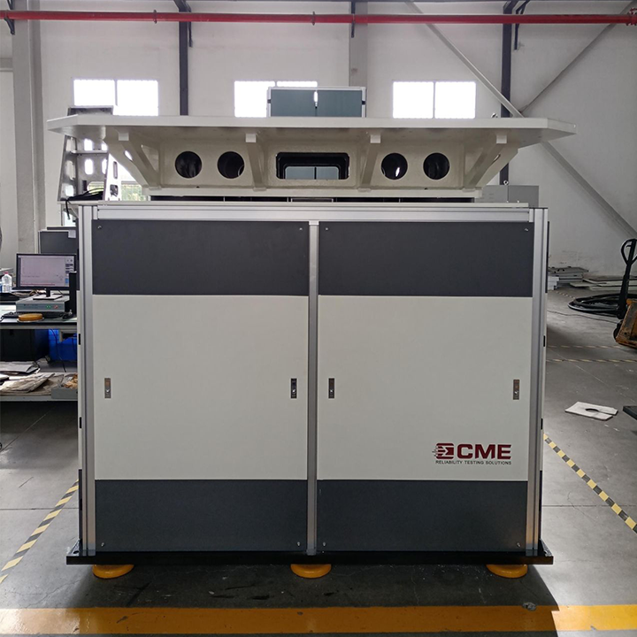
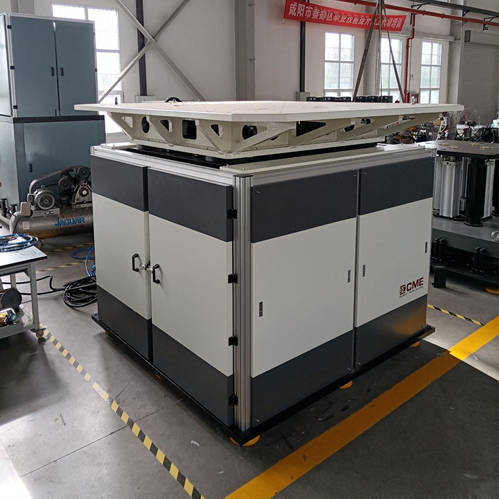
KRD17 series pneumatic bidirectional vertical shock test system is the novel designed and developed for large specimens that cannot or are not easy to turn over, especially adopt for battery testing. It can complete vertical upward and downward shock test in one test stand without moving the UUT.
Download Document
 Get a quote
KRD17 series pneumatic bidirectional vertical shock test system is the novel designed and developed for large specimens that cannot or are not easy to turn over, especially adopt for battery testing. It can complete vertical upward and downward shock test in one test stand without moving the UUT.
Pneumatic drive, no pollution to the environment
One machine with multiple functions, one clamping, to complete the upward and downward shock and bump tests, with high efficiency
Built-in pneumatic brake mechanism, safe and reliable
One-machine management for control and measurement, convenient operation
Air springs and dampers are used to reduce vibration, and the installation is free of foundation
Technical Specfications
Model Parameters | KRD17-50 | KRD17-100 | KRD17-200 | KRD17-500 | KRD17-800 | KRD17-1000 | KRD17-2000 | |
Rated Load (kg) | 50 | 100 | 200 | 500 | 800 | 1000 | 2000 | |
Table Size (mm) | 500×500 | 600×600 | 800×800 | 1000×1000 | 1200×1200 | 1500×1500 | 2000×2000 | |
Shock Direction | Downward | |||||||
Peak Acc. (g)
| Half-Sine | 10-750 | 10-600 | 10-450 | 10-300 | 10-250 | 10-200 | 10-150 |
Post-Peak Sawtooth | 10-200 | 10-200 | 10-100 | 10-100 | 10-100 | 10-100 | 10-100 | |
Trapezoid | 15-200 | 15-200 | 15-100 | 15-100 | 15-60 | 15-60 | 15-50 | |
Pulse Duration (ms) | Half-Sine | 1.5-60 | 2-60 | 2.5-60 | 4-60 | 4.5-60 | 5-60 | 6-60 |
Post-Peak Sawtooth | 3~18 | 6~18 | ||||||
Trapezoid | 3~18 | 3~18 | 6~18 | |||||
Shock Direction | Upward | |||||||
Shock Wave | Half Sine Waveform | |||||||
Peak Acceleration (G) | 15-350 | 15-300 | 15-200 | 15-150 | 15-100 | 15-100 | 15-75 | |
Pulse Duration (ms) | 3.5-60 | 3.5-60 | 4-60 | 4.5-40 | 5.5-60 | 5.5-60 | 6-60 | |
Overall Dimension (mm) | 1250×1250×1600 | 1250×1250×1600 | 1300×1300×1700 | 1350×1350×1750 | 1550×1550×1750 | 1650×1650×1850 | 2000×2000×1900 | |
Weight (kg) | 3000 | 3200 | 3500 | 5000 | 6000 | |||
Power | 1-phase AC220V±10% 50Hz | |||||||
Air Source | ≤1MPa | |||||||
Installation Condition | Foundation-free, the cement floor shall be leveled and the working distance of 800 ~ 1000mm shall be reserved around the equipment | |||||||
Working Environment | Temperature range 0 ~ 40℃, Humidity≤80% (non-condensing) | |||||||
Standards | IEC68-2-27 MIL-STD-202 MIL-STD-750 MIL-STD-810 MIL-STD-883 UN38.3 IEC62281 IEC62133-2 UL2054 IEEE1625 SAEJ2929 IEC62660-2 ISO12405-3 UL2580 | |||||||
Note: 1. The parameters in the table are for reference only, and the parameters agreed upon by the supplier and the buyer shall prevail.
2. Post-peak Sawtooth and Trapezoid waveforms are optional.
Application Video
CME Technology Co., Ltd.
Add.: No.3 Upgrade Demonstration Base, West of Yongchang Rd., High-tech Zone, Xianyang City, Shaanxi Province, 712023 China
Tell: +86 13588426277 (WhatsApp)
Fax: 029-33193132
Email: [email protected]
products Shock / Bump Test System SRS Test System Constant Acceleration Tester Drop Test System Transportation Simulation Test System Multi-Axial Simulation Table Vibration Shakers Packaging Test System