DATE: 2025-09-30
VIEW COUNT: 1936
MIL-STD-810H & GJB150A
MIL-STD-810H and GJB150A both test equipment for environmental adaptability and durability. MIL-STD-810H is a US military standard primarily used to test equipment's reliability and adaptability in various extreme environments, including high and low temperatures, humidity, vibration, shock, and other environmental conditions. It is widely used in various US military equipment, including communications equipment, vehicles, and weapons.
GJB150A is a Chinese military equipment environmental testing standard. Similar to MIL-STD-810H, it is primarily used for environmental adaptability testing of military equipment. It also covers test items such as temperature and humidity, vibration, dust, and corrosion, ensuring that equipment can operate properly in complex environments.
Acceleration testing is primarily covered in MIL-STD-810H Method 513.8 and GJB150A.15A.
Test Purpose and Application
The purpose of this test is to verify:
a) The equipment's structural ability to withstand steady-state inertial loads caused by platform acceleration, deceleration, and maneuvering in the operating environment, and that its performance does not degrade during and after these loads;
b) The equipment will not be hazardous after experiencing crash inertial overloads.
This test is applicable to equipment installed on aircraft, helicopters, manned spacecraft, aircraft external stores, and ground-launched missiles.
Test Method
A centrifuge generates acceleration loads by rotating about a fixed axis. Therefore, the acceleration is always directed radially toward the centrifuge's axis of rotation, while the acceleration-induced load is always directed radially outward from the axis of rotation.
When a specimen is mounted directly on the centrifuge's test arm, it experiences both rotational and translational motion. For a given rotational speed, the acceleration and the acceleration-induced loads on the specimen remain constant, but the specimen rotates 360° with each revolution of the arm. Some centrifuges are equipped with an anti-rotation fixture on the arm to compensate for this rotation. This fixture maintains the specimen's position in space, but the acceleration and the acceleration-induced loads rotate 360° around the specimen with each revolution of the arm.
Another characteristic of a centrifuge is that the acceleration-induced load is proportional to the specimen's distance from the axis of rotation. A centrifuge of appropriate size should be selected to ensure that the acceleration loads experienced by the specimen's parts closest to and farthest from the axis of rotation are no less than 90% and no more than 110% of the specified test values, respectively.
The tolerance for acceleration values at all points on the specimen is ±10% of the specified value.
The steps for installation in the centrifuge are as follows:
a) Mount the specimen on the centrifuge arm at a position that provides the required acceleration value for the test, with the specimen's geometric center located exactly at this position. The test value is calculated using the formula:
NT=krn²
In the formula:
NT — Test overload factor (overload factor perpendicular to the centrifuge rotation plane)
K — 1.118x10⁻³
R — Radial distance from the center of rotation to the specimen mounting position on the centrifuge arm, m
N — Centrifuge arm revolutions per minute, r/min
b) The six test force directions for the specimen in the centrifuge are as follows:
1) Forward: The front or leading end of the specimen faces the centrifuge center
2) Backward: The forward position is rotated 180°
3) Upward: The top surface of the specimen faces the centrifuge center
4) Downward: The upward position is rotated 180°
5) Leftward: The left side of the specimen faces the centrifuge center
6) Rightward: The right side of the specimen faces the centrifuge center
c) After the specimen is correctly oriented and mounted in the centrifuge, measurements and calculations should be performed to ensure that the acceleration value at the end of the specimen closest to the centrifuge center is no less than 90% of the specified test value. If the calculated acceleration value is less than 90% of the test specified value, the specimen should be installed slightly outward on the centrifuge arm and the speed should be adjusted accordingly, or a larger centrifuge should be used so that the end of the specimen closest to the center of the centrifuge is subjected to at least 90% of the specified acceleration value, while the acceleration value of the other end (the end farthest from the center of the centrifuge) should not exceed 110% of the specified acceleration value. For large specimens, given the current status of large centrifuges in domestic testing departments, the load gradient requirement can be relaxed.
Table 513.8-1. Suggested g levels for Procedure 1 - Structural Test 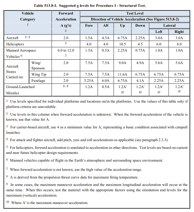
Table 513.8-2. Suggested g levels for Procedure 2 - Operational Test.
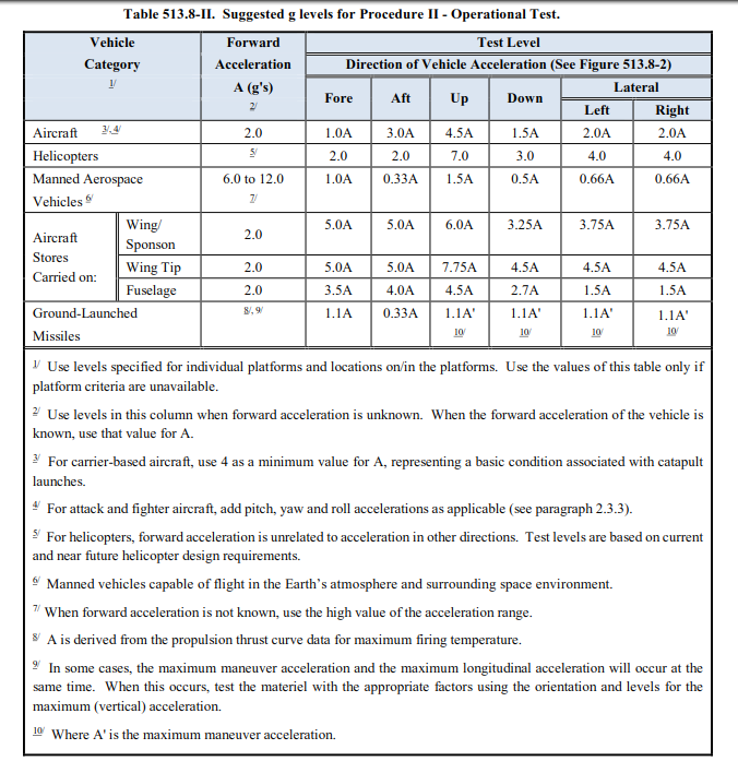
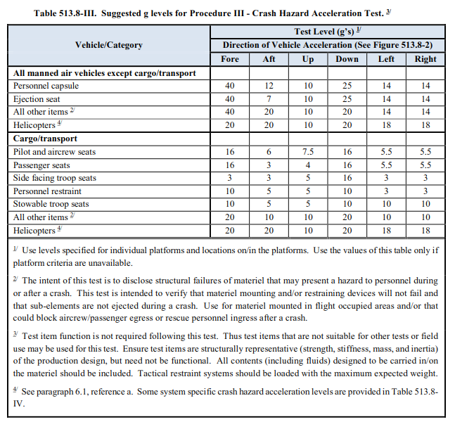
Table 513.8-3. Suggested g levels for Procedure 3- Crash Hazard Acceleration Test
Recommended Equipment
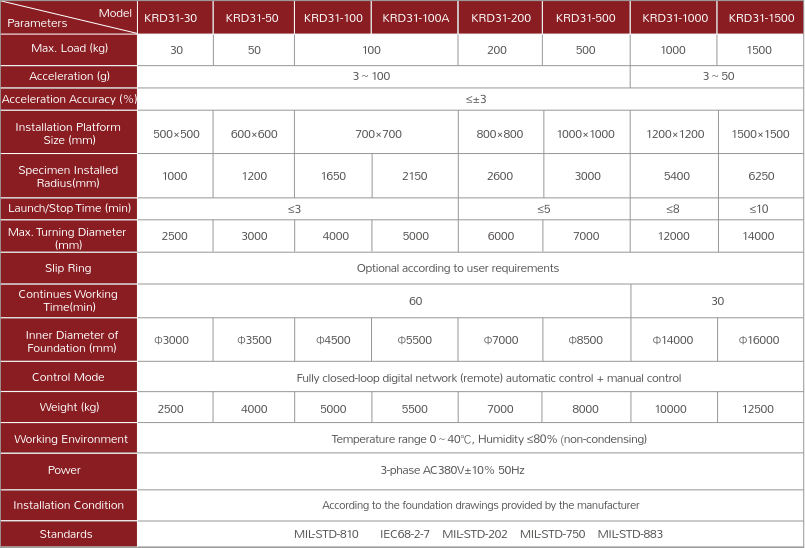
KRD31 Constant Acceleration Testing Machine (Arm Type)
KRD31 series arm-type constant acceleration tester is used to determine the structural adaptability and performance of electronic components, small devices, and other electrical and electronic products subjected to forces (excluding gravity) generated in constant acceleration environments, such as those caused by moving vehicles, aerial vehicles, rotating machinery, and projectiles. It also assesses the structural integrity of certain components.
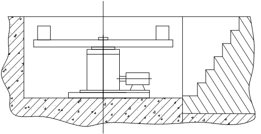
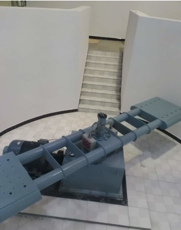
This equipment primarily consists of a conductive slip ring assembly, an arm assembly, a transmission system, a housing and base, an AC measurement and control system, a monitoring system, and a door and security system. A three-phase AC motor drives a pair of spiral bevel gears for speed reduction via an elastic pin coupling. The large bevel gears are mounted on the rotating main shaft, and the working arm is also fixed to the main shaft, driving the working arm to rotate around the main shaft. The specimen is mounted on the arm mounting surface at a predetermined radius from the main shaft. As the arm rotates at a constant speed around the main shaft, the specimen on the arm is subjected to a constant acceleration. By varying the specimen's mounting radius and the arm's rotational speed, the desired acceleration value can be achieved. See Figure 1 for a photo of this rotating arm constant acceleration centrifuge testing machine, Figure 2 for its operating principle, and Figure 3 for its main structure.
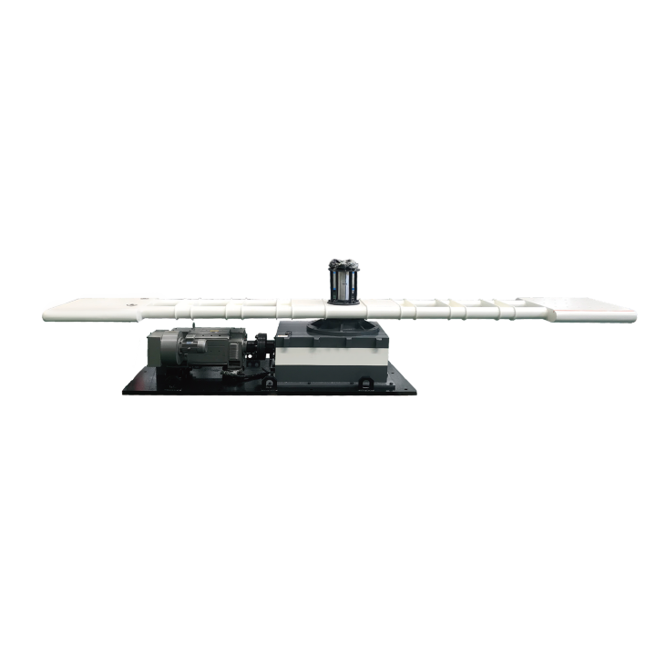
Figure 1 Reference picture of the rotating arm constant acceleration tester

Figure 2 Constant acceleration testing machine driving schematic diagram

Figure 3 Constant acceleration testing machine structure schematic diagram
Specifications