DATE: 2025-09-30
VIEW COUNT: 1764
MIL-STD-810H & GJB150A
Both MIL-STD-810H and GJB150A test equipment for environmental adaptability and durability. MIL-STD-810H is a US military standard designed to test equipment's reliability and adaptability in various extreme environments, including high and low temperatures, humidity, vibration, shock, and other environmental conditions. It is widely used in various US military equipment, including communications equipment, vehicles, and weapons.
GJB150A is a Chinese environmental testing standard for military equipment. Similar to MIL-STD-810H, it is primarily used for testing the environmental adaptability of military equipment. It also covers test items such as temperature and humidity, vibration, dust, and corrosion, ensuring that equipment can operate properly in complex environments.
Tilt and swing tests are primarily covered in MIL-STD-810H Method 527.2 and GJB150A.23A. Test Purpose and Application
The purpose of this test is to determine whether the equipment can:
a) maintain structural integrity under pitch and roll conditions;
b) operate under pitch and roll conditions.
This test is applicable to the evaluation of:
a) equipment used, transported, or stored on surface ships;
b) equipment used, transported, or stored in submarines.
Test Procedure
This test consists of three test procedures: pitch, roll, and combined pitch and roll tests. Unless otherwise specified, the pitch test is generally conducted before the roll test. The combined pitch and roll test can also be conducted simultaneously.
The differences between the procedures are as follows:
a) Pitch: Applicable to equipment that must function properly when the ship pitches.
b) Roll: Applicable to equipment that must function properly when the ship rolls in wind and waves.
c) Combined pitch and roll: Applicable to equipment that must function properly when the ship pitches and rolls simultaneously.
Test Method
After selecting this test and the corresponding procedure, the test conditions and test techniques used in the procedure should be selected based on the relevant documents and information provided for the procedure, and the equipment's ability to perform in pitch and roll conditions should be determined. Pitch and roll tests should be conducted on any equipment whose performance is affected by pitch and roll conditions, or for any structure involving rotational motion, liquid media, or gravity imbalance. Test parameters, including the test pitch and roll angles, test pitch and roll angles, test roll cycle, and test duration, as well as the technical condition of the test piece, should be determined. The following should be considered when determining these parameters:
Test Tilt and Roll Angles
The test pitch and roll angles should be determined based on the equipment's intended use, product specifications, or actual measurement data. Unless otherwise specified, the test pitch and roll angles may be determined with reference to Tables 1 and 2.
Test Roll Cycle
The roll cycle should be determined based on the ship's displacement and sea conditions. The pitch and roll cycles may vary for the same ship. When the equipment's technical documentation provides the actual roll cycle, the test cycle should be determined based on actual operating conditions. Unless otherwise specified, the roll test cycle may be determined with reference to Tables 1 and 2.
Test Duration
The test duration for each of the three procedures should represent the expected operating time under pitch and roll conditions. However, for most equipment, if this period is too long, the test duration should be at least 30 minutes. Test Item Technical Condition
The technical condition of the test item should be determined based on the expected actual conditions of equipment transportation, storage, or operation. At least the following technical conditions should be considered during testing:
a) In the transport and storage container or shipping box;
b) In its normal operating technical condition
A rocking test rig is used for rocking or combined pitch and roll tests. When performing a tilt test on the rocking test rig, the specimen must remain stable in the specified position under the maximum test load, without noticeable shaking or drifting.
The rocking test rig must be able to simulate at least one type of ship rocking, typically roll or pitch. The rocking angle and period must be freely adjustable and meet the required ±5% test tolerance. Waveform distortion must be less than 15%.
Recommended Equipment
KRD60 3-DOF Test System
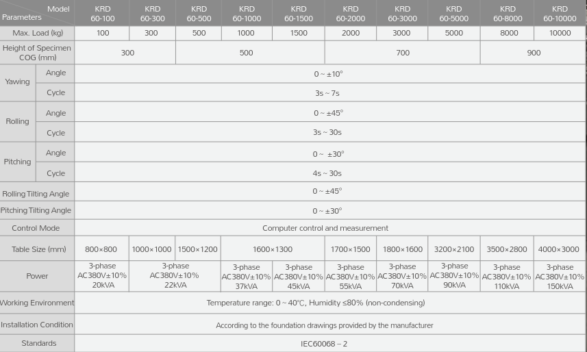
The KRD60 series 3-DOF test system can simulate rocking and tilting tests on various mechanical, electrical, and electronic products installed on ships, seaplanes, and other equipment to determine their ability to withstand the specified severity of rocking and tilting, as well as their structural integrity. Tilt tests are primarily applicable to ship damage, imbalances in handling and loading, and large angles of tilt caused by wind. Rocking tests are primarily suitable for products that must maintain normal or reliable operation during prolonged rocking caused by external forces such as wind and waves, as well as for products whose performance would be significantly affected by rocking conditions. Features
- Based on the stable Windows operating system, it supports an automatic remote-control interface, allowing operators to accurately complete tilt and roll tests by simply entering simple numerical values.
- The user interface primarily displays real-time data curves and also displays test parameters, system status, and test progress.
- It supports sinusoidal signals, closed-loop control, various function controls, and alarm prompts.
- Roll, pitch, yaw, and tilt tests are performed on the same platform.
Specifications
KRD61 6-DOF Test System
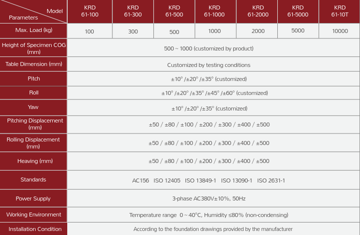
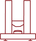
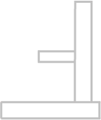
KRD61 6-DOF test system is a closed-loop servo simulation platform consisting of six actuators and six universal joints on each upper and lower surfaces. The telescopic motion of the six actuators enables the upper platform to move in six degrees of freedom (X, Y, Z, α, β, γ) in space, thus simulating various spatial motion postures.
It can be widely used as a test or training simulator in fields such as aviation, naval vessels, helicopter takeoff and landing, car and train driving, earthquakes, film, and entertainment equipment. It can even be used for docking spacecraft and refueling tankers. In the machining industry, it can be built into six-axis machine tools and intelligent robots.
1. It can perform posture simulation, sinusoidal wave simulation, single-degree-of-freedom motion, and multi-degree-of-freedom compound motion.
2. It can perform path spectrum filtering and replication of path, wave, and flight spectra.
3. Provides a third-party control interface for PCs via TCP/IP.
4. Provides internal and external data output control interfaces.
Specifications